Eventually, the cost per bit of 64K-bit RAM dropped below that of its predecessor, 16K-bit dynamic RAM. The most common 8-bit microprocessors of the time were using an optimal 64K-byte address space, powered by eight of these 64K-bit chips.
However, the market dynamics have changed. At that time, the cost per bit of 256K-bit dynamic RAM had reached its lowest point, making it a popular choice in powerful 16- and 32-bit microcomputer systems.
It was possible to upgrade an inexpensive 64K-byte microcomputer to 256K bytes by using eight of these chips, which resembled their predecessors. Attempting to fit 256K bytes of memory into the 64K-byte address space of a 6502 or Z80 all at once is not feasible. However, breaking it down into manageable banks and allowing the processor to access one bank at a time offers a viable solution. This approach to RAM interfacing is known as bank selection and requires new hardware and software support.
This article discusses Claus Buchholz's Atari 256K RAM upgrade and presents a RAM-disk controller tailored for the Atari 800XL. However, this concept can be used on any microcomputer that uses 64K-bit RAMs, such as the Apple IIe, Commodore 64, MSX machines, and others.
The Atari 800XL
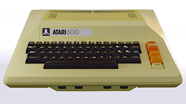
The 800XL was a modern version of the Atari 800, which was introduced in 1979. The 800 was the first machine to use VLSI technology, which brought advanced graphics and sound capabilities to the low-price market segment. It was also the first to have a full operating system integrated into ROM to support its versatile hardware setup. RAM configurations usually consisted of up to three 16K-byte modules. Each module was constructed around eight 16K-bit dynamic RAM chips, which can be changed to make an Atari 256K RAM upgrade.
The 800 model had a programmable video DMA (direct memory access) controller that coexisted with the 6502 processor within the system. Whenever the controller needed to access a byte of screen memory, it would momentarily halt the 6502 for one cycle of the 1.8-MHz clock. The 800XL retained the same VLSI hardware as its predecessor but with updated, higher-density RAM and ROM configurations. The operating system was stored in a single 16K-byte ROM, while another 8K-byte ROM contained the BASIC language. RAM arrangements were streamlined, consisting of eight 64K-bit dynamic RAM chips. When using BASIC, 40K bytes of RAM were available. Additionally, the ROMs, which occupied high memory space, could be disabled to provide access to the remaining RAM capacity.
The redesigned 800XL had a smaller footprint, reduced cost, lower power consumption, and enhanced aesthetic appeal. Undoubtedly, the Atari was a remarkable computing machine in computer history.
The Dynamic RAM
The dynamic RAM chip is an industry-standard example of exceptional design. It is compact, dense, fast, and affordable. Its memory capacity has doubled eight times over the past decade without outgrowing its 16-pin IC package. Each chip can input or output one bit at a time, and each bit has a unique address.
The 256K-bit chip requires 18 bits for its address. The chip has nine address inputs, each with a dual purpose. In the initial phase of memory access, the chip receives half of the address bits, which is known as the row address. Later in the access cycle, the remaining half of the address is presented to the chip, referred to as the column address. The memory cells within the chip form a matrix, with the addressed cell located at the intersection of the specified row and column. To conclude the access cycle, the chip reads or writes to the selected bit.
The Atari 800XL uses 64K-bit RAM chips with eight address inputs, accommodating an 8-bit row address and an 8-bit column address. This arrangement aligns well with the 16-bit addresses supplied by the 6502 processor. With eight chips in use, each contributes one bit to every byte of RAM.
The 256K-bit RAM chip is almost the same as the 64K-bit version, except for the addition of an extra pin, Pin #1. This pin accommodates the two additional address bits required. Pin #1 on the 64K-bit chip has no function. However, all other pins on both chips have identical functions. For this Atari 256K RAM upgrade, replace the eight 64K-bit RAMs with eight 256K-bit chips and add circuitry to supply two extra address bits for Pin #1.
Dynamic RAM chips contain memory cells that function as microscopic capacitors, storing electric charge to represent 0 or 1 bits. These capacitors require periodic recharging or refreshing due to charge leakage. When accessed, the chip refreshes one or two entire rows. To maintain data accuracy, the computer system must provide special refresh cycles, which are dummy read cycles using refresh addresses as row addresses.
The 16K- and 64K-bit RAMs require 7-bit refresh addresses. This means that the computer must provide all 128 possible refresh addresses every few milliseconds to ensure that the RAM remains refreshed. In the Atari system, the video controller automatically provides 7 bits for the refresh address in addition to screen-memory accesses. It is worth noting that the Atari allocates 8% of its time to refreshing RAM.
Designing the 256K-byte upgrade presents a challenge due to the RAM's 8-bit refresh address requirement. The older versions of the Atari video-controller chip only provide 7 bits of refresh address, while newer iterations provide all 8 bits. As a result, two versions of the upgrade's interface circuit were developed, with the more complex one requiring the addition of another bit to the Atari's refresh address.
Bank Selection for the Atari 256K RAM Upgrade
To fit 256K bytes into the 6502's 64 K-byte memory space, it is necessary to divide it into banks. The upgrade uses eight 32K-byte banks, numbered from 0 through 7, and selected by configuring 3 bits in Atari's memory-control register. Each bank can occupy the lower half of the 6502's memory space. Upon power-up, bank #7 is allocated to the lower 32 K bytes of RAM, while bank #6 occupies the top 32 K bytes, allowing the Atari to function as a standard 64K-byte machine. To access bytes in the remaining 192K, a program must designate one of the banks #0 through #5 to replace bank #7. After completing byte access, the program can switch bank #7 back in to restore the normal configuration.
The decision to use eight 32K-byte banks instead of four 64K-byte banks was influenced by several factors. Firstly, replacing the entire 64K bytes of RAM with another bank could cause the program in RAM to disappear, leading to system crashes. In addition, the first 32 kilobytes of the address space were already taken up by hardware addresses and ROMs that could be swapped in and out. Moreover, the screen RAM usually occupied the top 32K, and replacing it could cause screen glitches.
Despite having eight 32K-byte banks, caution was necessary. The operating system stores crucial data in the lower part of RAM, with the assumption that it will remain there. Furthermore, interrupts often trigger routines that depend on data in low RAM. Therefore, programs must follow a strict rule: keep bank #7 enabled as much as possible. If another bank is selected, disable all interrupts and do not call the operating system until bank #7 is restored. Additionally, the 6502's stack, located in low memory, was taken into account. Programs should avoid using the stack when bank #7 is not selected unless they take great care to maintain stack validity.
Table 1. The components needed to upgrade the Atari 800XL.
| Quantity | Part | Notes |
| 8 | 41256 chips 256K-bit dynamic RAM | (200 ns or faster) |
| 1 | 33-ohm, 1/4-watt resistor | |
| 1 | 74LS153 Dual 4-to-1 multiplexer | (for the circuit in Figure 1 only) |
| 1 | 74LS151 8-to-1 multiplexer | (for the circuit in Figure 2 only) |
| 1 | 74LS393 Dual 4-bit counter | ( " ) |
| 1 | 74LS00 Quad NAND gate | ( " ) |
Interfacing the Atari 256K RAM Upgrade
The interface circuit designed for the 256K-byte RAM is shown in Figure 1. To install this circuit, it needs to be assembled on a small circuit board and replace one of the chips on the motherboard. To install this circuit, it needs to be assembled on a small circuit board and replace one of the chips on the motherboard. Four jumper wires are required to connect various points on the motherboard since the computer's expansion slots do not carry the required signals.

The circuit was designed to plug into position U27 on the motherboard, providing access to six critical signals, including power and ground. The chip that was originally at U27 now serves as IC1 within the circuit. In its original position as U27, this chip selects which 8 of the 16 address bits are passed to the 64K-bit RAMs at any given time.
IC2 is responsible for selecting the bank by modifying one of the eight original address inputs to the RAMs and adding a ninth. To achieve this, three jumpers are required to carry 3 bits from Atari's memory-control register, with a fourth jumper carrying the ninth address input to the RAMs.
Figure 2 shows the four-chip interface circuit that is essential for machines containing the older version of the video controller. The 256K-byte RAM interface circuit uses IC3, an 8-bit binary counter, to count refresh cycles and supply the eighth bit of the refresh address. The refresh signal is sourced through a jumper wire from the motherboard. IC1, IC2, and IC4 components contribute to bank selection in this setup.
Performing the Atari 256K RAM Upgrade
To disassemble the 800XL, start by removing the six screws located on the underside of the unit. Then, separate the top and bottom portions of the plastic case cautiously, taking care not to damage the flexible keyboard cable. Finally, pull the cable straight up out of its socket on the motherboard. To detach the motherboard from the case bottom, remove three screws: one on the right side, one in the right rear corner, and one in the left rear corner. Then, gently pull the board free. Next, remove the small nuts and bolts around the metal shielding that encased the motherboard. On the left side of the exposed motherboard, locate the row of eight 16-pin RAM chips. Just to their right is U27. The 3-inch square area behind U27 fits inside the shielding. This positioning was chosen because the shielding is highest toward the rear.
Replacing the 64K-bit RAM chips with the 256K-bit RAM chips requires extreme caution. The new RAMs are highly susceptible to damage from static discharges, so it is necessary to handle them with extreme care. To mitigate the risk, aluminum foil can be laid on the work surface. Keep the motherboard, RAM chips, tools, and hands in contact with the foil at all times to maintain the same potential and decrease the possibility of damage.
To locate the video controller on the motherboard, look for the 40-pin chip labeled U7. If the part number stamped on it is 'C021697,' use the simpler circuit shown in Figure 1. If the number reads 'C012296,' use the larger circuit.
You will need to assemble the appropriate circuit on a 2-by-3-inch circuit board. We recommend using Radio Shack's #276-150. To ensure proper shielding, it is recommended to use low-profile sockets or avoid them altogether. If sockets are not used, be cautious not to apply heat to the IC pins for too long. To save space, keep the wiring on the chip side of the board and solder it, as there is no room for wire-wrap posts.

The board is designed to plug into the socket at U27 via a 16-pin DIP header and a short ribbon cable. To install the jumper wires, start by removing the resistor marked R32 located behind the row of RAM chips. Then, solder the first jumper to the corresponding hole. Connect the next three jumpers to the parallel port used by the Atari to control ROM switching, using pins 14 through 16, which are normally unused and not connected to any traces. Locate U23 and carefully remove the 40-pin chip from its socket. Bend pins 14, 15, and 16 straight out. Cut three adjacent pin positions from an IC socket and solder the jumpers to them, connecting them to the three protruding pins. Cover the connector with electrical tape because the shielding is very low at this point.
If using the circuit in Figure 2, a fifth jumper is required. Locate the trace on the motherboard from pin 8 of the video controller U7. Solder a jumper to a hole along the trace. Insert a thin piece of stiff cardboard or plastic under the small circuit board to prevent shorting the circuit. Refasten the shielding to the motherboard. If the shielding doesn't fit over the circuit, carefully pound out any dents with a hammer. After reassembling the computer, if everything went smoothly, it should power on normally and function just as it did before, as long as the 3 bits in the memory-control register are not altered. At that point, the computer will be prepared to run software that can utilize the additional RAM space.
The RAM-Disk Software for the Atari 800XL RAM Upgrade
The bank-selectable RAM is only useful with software designed to control it. The software must strictly follow the outlined rules to ensure proper functionality. Additionally, the software must be customized for the intended application.
For example, the bank-selectable RAM can be used to store multiple graphics screens and use page flipping to display them quickly for animation purposes. The RAM can function as a print spooler, allowing a word processor to quickly print a document into the RAM. This allows the user to proceed to other tasks while the RAM slowly empties its contents into a printer.
Another application is the RAM disk, which simulates a disk drive using RAM. The RAM disk appears as just another disk drive to both the disk operating system (DOS) and the user's programs but with significantly faster access times. Standard DOS commands can be used by application programs to access the large RAM space. The available RAM of 192K bytes can hold more data than two Atari 810 drives or one double-density drive.
An assembly-language program was developed to modify the Atari's operating system, treating the Atari 256K RAM upgrade as either a single-density or double-density disk drive. This program is available for download as ATARIRAM.ASM. The software is compatible with Atari DOS 2.0, OS/A+ (versions through 2.xx), and other compatible DOSes. To assemble the source code, use any assembler that accepts the syntax of the Atari Assembler/Editor. The assembly process produces an object file that performs several tasks upon loading. It first copies the operating system from ROM into the underlying RAM. The RAM-disk routines are loaded into the RAM-based operating system next. This overwrites the international character set, which is a feature that is rarely used in the 800XL. Finally, the operating system is patched to install the RAM-disk program, and DOS's initialization routine is called to enable DOS to recognize the new drive.
The source code offers two options: the drive number and the density. The RAM disk can emulate any drive numbered 1 to 8. For example, if there is only one physical drive, it may be better to assign the RAM disk as drive number 2.
It is important to configure DOS to recognize the selected drive number. Instructions for setting up drive numbers can be found in the DOS manual.
The Atari 810 disk drive and a single-density RAM disk both have 720 sectors, 128 bytes each, for a total of 90K bytes. On the other hand, a double-density RAM disk, like all double-density disk drives for the Atari, has 720 sectors of 256 bytes each, providing a total capacity of 180K bytes. Atari DOS automatically detects the density of each drive in the system and adjusts accordingly. All DOS functions, except disk duplication, are compatible with double-density drives. Duplicating a double-density disk to a single-density disk, and vice versa is not possible.
To start the RAM-disk object file after DOS, rename the object file as AUTORUN.SYS. After loading, format the RAM disk before use. You can do this manually from DOS, via the BASIC XIO command, initiated through a call to CIO in machine code, or handled by an application program.
The contents of the RAM disk are not at risk from RESET or warm starts. However, if you reboot the computer without powering it down by using POKE 580,1 and RESET or by jumping to $E477 in machine code, you must reload the RAM-disk program to access the data. The data stored in the RAM disk remains unaffected during these operations because the RAM disk program does not automatically format the RAM disk upon loading.
The primary drawback of the RAM-disk approach is that all data is lost when the computer is turned off. It is essential to save important data to a physical disk before powering down. However, the advantages of speed, convenience, and versatility offered by the Atari 256K RAM upgrade are considered to outweigh its drawbacks.
Use Cases for the 256 Atari 800XL RAM Upgrade
Assembly-language programmers can explore numerous practical applications for a quarter-megabyte of RAM after analyzing the RAM-disk source code and following the outlined rules. The Atari system's versatile hardware, coupled with its affordability and expansive RAM capacity, provides an unparalleled performance-to-price ratio in the current market.
For additional info on the Atari Quarter-Meg Upgrade click here.


