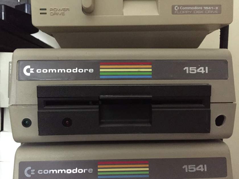
While the later 1541-II model is relatively easy to power with a standard PC supply, it lacks the mounting compatibility of the original. The original, "old-style" 1541, with its hefty chassis and classic mechanism, actually fits beautifully into a PC case. In fact, if you hold the old 1541 mechanism up to a standard 5.25" drive bay, you’ll notice something surprising: Commodore actually followed some industry standards. The screw holes often align perfectly with the rails of a tower case, making it a perfect candidate for this conversion.
However, the original 1541 requires specific voltages (+5V and +12V) that a PC power supply provides in abundance. Here is a guide on how to safely tap into that power and get your 1541 running with the flick of your PC's power switch.
The Schematic: Tapping into the 1541 PCB
Before you begin, please note that this guide is intended specifically for the original, large PCB found in early 1541 drives. If your drive has a different board revision, proceed with caution or verify the points with a multimeter first.
The graph in Figure 1 illustrates the ideal connection points on the 1541 PCB. Instead of cutting the original trace or soldering directly to the power switch, we are going to connect directly to the board's main power filter capacitors and diodes. These points are excellent because they are robust, designed to handle current, and (in the case of capacitors) filter out noise from the power supply.
Ground (GND / 0V): This is the easiest connection. Look for the large filter capacitor labeled C1 on the board. The negative leg of this capacitor is connected directly to the ground plane of the drive. Since this leg is usually close to the border of the PCB, it provides a convenient soldering point for your black ground wire.
+12V DC: For the 12-volt line, locate capacitor C2. The positive leg of this capacitor is a prime spot to attach your yellow wire. Like C1, it is generally situated near the edge of the board, making it easy to route your wires out of the case.
+5V DC: The 5-volt line is just as critical as the ground. A great spot to attach the red wire is the positive leg of diode CR4 (typically a 1N4001). This is a common rectifier diode on the board, and its lead provides a solid connection point for your +5V feed.
A Word of Caution: If you are not experienced in soldering, be very careful. These points can be close together. Ensure you use a clean, hot iron and apply just enough solder to make a strong mechanical and electrical connection. After you are done soldering, always inspect your work with a bright light. Use a stiff brush (like an old toothbrush) to gently sweep away any loose metallic particles or stray solder balls that could cause a short-circuit.
Connecting to the PC Power Supply for Commodore 1541 Disk Drive
Once your wires are securely soldered to the 1541 board, it’s time to connect them to the power source. A standard ATX or older PC power supply uses standardized connectors (as seen in Figure 2). These are the same connectors used for hard drives and CD-ROMs from the 90s and 2000s.
These connectors are keyed to prevent incorrect insertion, but we aren't plugging the drive directly in; we are splicing wires. Here is the color code you need to know:
Black Wires: These are Ground (0V). All black wires in a Molex connector are common grounds.
Yellow Wire: This provides +12V DC.
Red Wire: This provides +5V DC.
The Final Connection:
Now, all you have to do is connect your three soldered wires to the corresponding wires of the PC power supply cord.
Connect your black wire (from C1) to one of the black wires on the Molex connector.
Connect your yellow wire (from C2) to the yellow wire on the Molex.
Connect your red wire (from CR4) to the red wire on the Molex.
You can do this by cutting a Molex extension cable and soldering the connections, or by using screw terminals and electrical tape for a non-permanent setup. Ensure all connections are insulated to prevent shorts.
The Final Assembly for the C1541 Power Supply
With the wires connected, you are ready for the moment of truth. Mount the 1541 mechanism into one of the 5.25" drive bays of your PC tower. As mentioned earlier, you might be pleasantly surprised at how well the mounting holes line up.
Once secured, plug in the PC power supply, flip the switch on the back of the PSU (if it has one), and press the power button of your PC case. The power from the supply will travel through your custom wiring and bring your vintage 1541 to life. BTW, don't forget to short PS_ON pin to the ground on the ATX PSU mainboard socket. It's pin-16 on a 24-pin socket, and pin-14 on a 20-pin socket. Its either side is ground.
That’s it! From now on, your 1541 will power up and down in perfect sync with your modernized Commodore 64-Tower. It’s a neat way to preserve the authenticity of the original hardware while integrating it seamlessly into a custom build.
PS: I've built my first C64-Tower in mid-90's, and in part of the C64 Tower Project, this howto was first published in March 1998 here: Connecting PC Case Supply to 1541 Drive


